How to Create Physical Standby Database by Using Oracle Enterprise Manager Cloud Control
Prerequisites for Using Oracle Enterprise Manager Cloud Control 12c
Oracle Enterprise Manager Cloud Control 12c can automate much of the process of creating both physical and logical standby databases. Before using Oracle Enterprise Manager for a Data Guard environment, some prerequisite steps must be performed. At a minimum, Oracle Enterprise Manager should be installed and configured on a server host. For each additional server that is to participate in a Data Guard environment, the software binaries for both the Oracle Database and the Oracle Enterprise Manager agent must be installed. These are installed into distinct Oracle Home locations. A default installation of the Oracle Enterprise Manager agent does not install plug-ins to the agent. Deploy the latest version of the Oracle Database plug-in to each agent and verify the status of the agents. Create a basic security configuration by defining named credentials for normal and privileged users for the host target type. Define individual target credentials for each host by referencing the named credentials.
Accessing the Add Standby Database Wizard
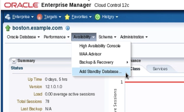
The screenshot above shows the home page for the primary database, with the top level menu structure containing the following items: Oracle Database, Performance, Availability, Schema, and Administration. To access the Add Standby Database wizard, navigate to the primary database target and select Add Standby Database from the Availability menu. The Add Standby Database menu item is the only Data Guard option on the Availability menu if a Data Guard configuration does not already exist. After a Data Guard configuration is defined, the Availability menu will also contain menu items for Data Guard Administration, Data Guard Performance, and Verify Data Guard Configuration.
Before you invoke the Add Standby Database wizard, verify that the primary database instance was started with a server parameter file (SPFILE) and that archiving is enabled.
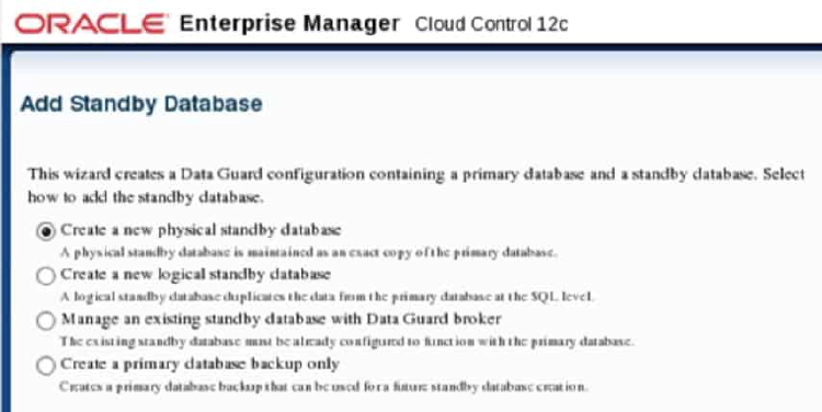
The above webpage snippet shows the Add Standby Database wizard after logging in for the first time. It provides the following options:
- Create a new physical standby database
- Create a new logical standby database
- Manage an existing standby database with Data Guard broker
- Create a primary database backup only
If you are not connected to the primary database when you select Add Standby Database from the Availability menu, a Database Login window appears. You will then be able to select from an existing named credential, or you can create a new credential. You must be connected to the primary database with SYSDBA credentials to use the Add Standby Database wizard.
Creating a New Standby Database
The Add Standby Database wizard can create both physical and logical standby databases. The wizard will prepare the primary database to support Data Guard operations including additional tasks such as:
- Performs an online backup (or optionally uses an existing backup) of the primary database control file, datafiles, and archived redo log files
- Transfers the backup pieces from the primary host to the standby host
- Creates other needed files (for example, initialization and password files) on the standby host
- Restores the control files, datafiles, and archived redo log files to the specified locations on the standby host
- Adds online redo logs and other files to the standby database as needed
- Configures the recovered database as a physical or logical
- Creating standby redo logs on the primary if needed
- Starting the Data Guard broker process
- Creating the Data Guard broker configuration files
- Adding primary and standby database to the Data Guard broker configuration
- Enabling the Data Guard broker configuration
- Adjusting initialization parameters such as LOG_ARCHIVE_CONFIG, LOG_ARCHIVE_DEST_n, and STANDBY_FILE_MANAGEMENT.
Step 1: Backup Type
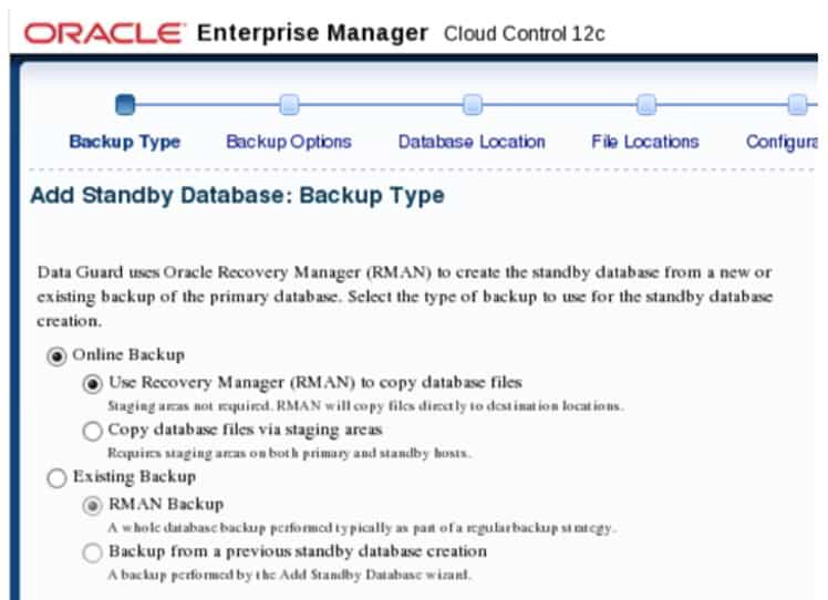
The screenshot above shows step one of six steps in creating a physical standby database. Step one defines the type of backup to be used for creating the standby database—either one that you create by performing an online backup, or an existing backup. Data Guard uses Oracle Recovery Manager (RMAN) to perform the backup.
The online backup option can be performed using a direct copy approach that does not require staging areas, or it can utilize staging directories. The staging directories can be retained for future standby database creations, or they can be deleted after the standby database is created. A backup performed into a staging area can be compressed to reduce file size and transfer time, but it may also slow down datafile backup and restoration.
The existing backup option requires a level 0 (full) or level 1 (incremental) RMAN backup that is typically performed as part of a regular backup strategy. You will be prompted for both the existing RMAN backup location and a new staging area location on the primary database host if you select this option.
Step 2: Backup Options
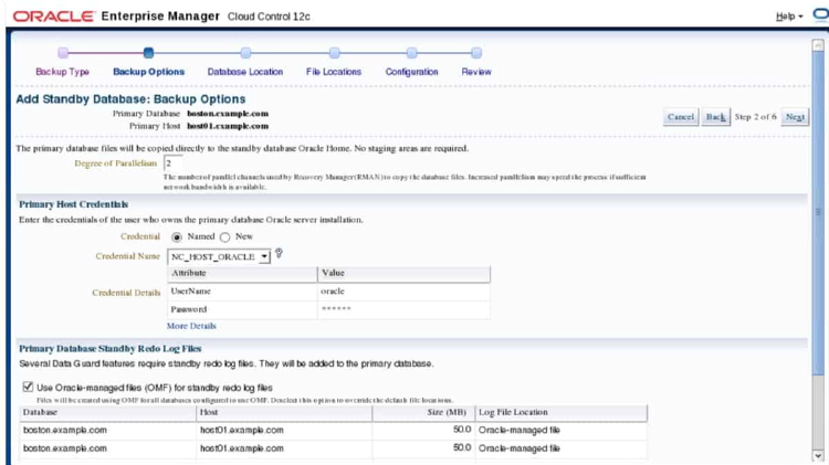
The screenshot above shows step two of six steps in creating a physical standby database. Step two is titled “Backup Options”. For an online direct backup, the degree of parallelism is specified as a backup option. In this step, you must supply the primary host credentials, using either an existing named credential or by creating a new credential. If the primary database does not currently have standby redo logs, this step will also require that they be created. Oracle Enterprise manager will automatically determine the correct size and number of groups to create for standby redo logs. You can select the option to use Oracle- managed files (OMF) for the standby redo log files or you can explicitly name and locate the standby redo logs that will be created on the primary database.
For backup types other than online direct backups, you supply the staging area locations, existing RMAN backup locations, backup compression features, and whether to retain the backups for future use depending on which backup method was chosen.
Step 3: Database Location
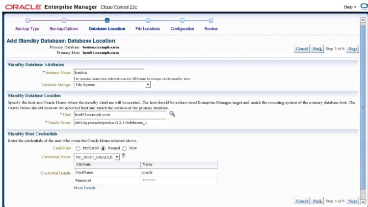
The screenshot above shows step three of six steps in creating a physical standby database. Step three is titled “Database Location”. This step contains three sections. In the Standby Database Attributes section, you define the instance name of the standby database and whether the standby database will use file system storage or Automatic Storage Management (ASM). In the Standby Database Location section, you define the host name for the server to which the standby database will be transferred and the existing Oracle home software location on that server. In the Standby Host Credentials section, you specify host credentials to be used on the standby server machine (you can use existing named credentials or you may create new credentials).
Step 4: File Locations
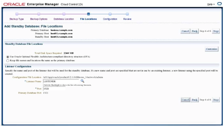
The screenshot above shows step four of six steps in creating a physical standby database. Step four is titled “File Locations”. This step contains two sections, Standby Database File Locations and Listener Configuration. If a file system was selected in step three as the database storage location, the Standby Database File Location section of this window allows you to keep the same files names and locations as the primary database uses, or allows you to create a new directory structure compliant with Oracle Optimal Flexible Architecture (OFA). If ASM was chosen in step three as the database storage location, Oracle Enterprise Manager will prompt you to log in to the ASM instance to determine available ASM disk groups and allow you to specify which ASM disk groups to use for storage. With either option selected, a Customize button in this section allows you to view all individual datafiles, tempfiles, logfiles, control files, directory objects, and external files, and to define specific names and locations.
If staging directories had been selected earlier, an additional section, Standby Host Backup File Access, appears. This allows the specific directory on the standby host machine to be defined along with the file transfer method, either HTTP/S or FTP. There is also an option for the standby database to access the files directly from a shared directory such as an NFS mount.
In the Listener Configuration section of this step, you specify the listener name and port number for the listener. A new listener will be created if the specified listener name and port does not already exist.
Step 5: Configuration
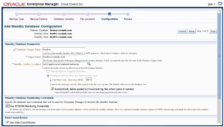
The screenshot above shows step five of six steps in creating a physical standby database. Step five is titled “Configuration”. This step contains four sections. The first section, Standby Database Parameters, prompts for the standby DB_NAME parameter (for logical standby databases only), standby DB_UNIQUE_NAME parameter, STANDBY_ARCHIVE_DEST parameter, and FAST_RECOVERY_AREA_SIZE parameter. You can also select to delete applied archive redo logs when space is needed.
The Standby Database Monitoring Credentials section of this step allows you to override normal default monitoring credentials and specify SYSDBA credentials for monitoring. This is required for a mounted standby database. The Data Guard Broker section is only displayed if no existing broker configuration is found. It allows you to delete the broker configuration after the standby database is created if desired. If there is an existing broker configuration, this section is hidden.
The Data Guard Connect Identifiers section allows you to specify connect identifiers for both the primary database and standby database. You can use Enterprise Manager connect descriptors that are explicitly coded into the LOG_ARCHIVE_DEST_n parameters, or specify an existing net service name that can be used by all databases. If a connect identifier for the primary database has already been created previously for other standby databases, you will not be prompted for it again here.
Step 6: Review
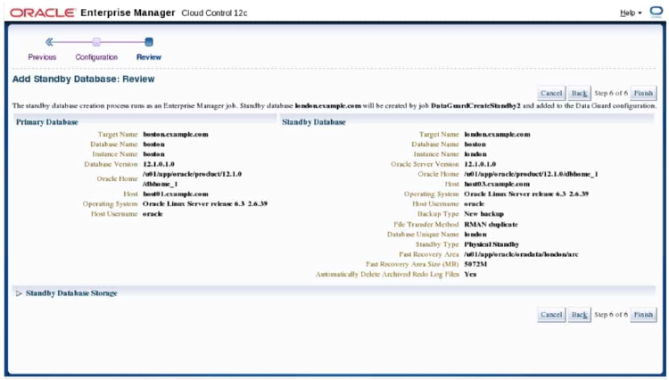
The screenshot above shows step six of six steps in creating a physical standby database. Step six is titled “Review” and it provides a recap of many of the settings entered on the previous five steps. The Standby Database Storage section can be expanded to show all individual datafiles, tempfiles, logfiles, control files, directory objects, and external files that will be created on the standby database host. If everything is satisfactory, click Finish to create a job to perform the tasks.
Creating a Physical Standby Database: Job Activity
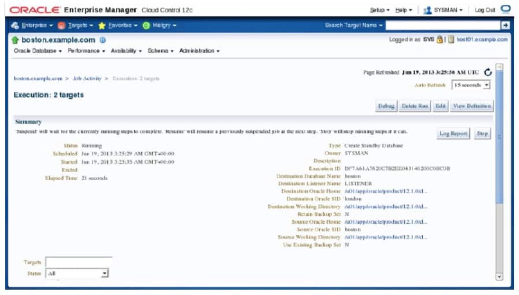
When you click the Finish button in step six of the Add Standby Database wizard, an Oracle Enterprise Manager job is created and an information dialog window appears that provides a URL link to view the job. The screenshot in the slide shows the job activity window for the job that was created. The default refresh mode for this window is manual refresh. Change the auto-refresh option to one of the available time-frequency choices to see changes happen while they are in progress or manually click the refresh icon when desired. The Log Report button will show the output log for all SQL*Plus, RMAN, and Listener Control Utility (lsnrctl) utility commands used. The Debug button will provide more details in the logs, including the actual RMAN script that was used to duplicate the primary database.
Job Task Details
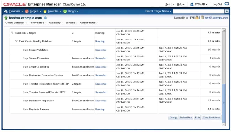
The screenshot above shows the job activity window. The scroll bar on the right side of the window has been moved down to show individual job steps of the Create Standby Database job. Each row or job step shows the target machine that the job step was run on, the status of the job step, the start time of the job step, the end time of the job step, and a calculated elapsed time for the job step.
Data Guard Administration Page
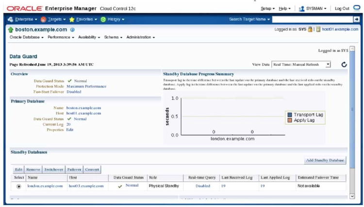
After a Data Guard configuration has been defined, the Availability menu contains both Add Standby Database and Data Guard Administration items. Clicking either one while on the primary database home page opens the Data Guard administration page.
The screenshot above shows the Data Guard administration page. The Overview section on this page displays the Data Guard status for the configuration, the protection mode, and whether Fast-Start Failover has been enabled. The Primary Database section of this page shows the hostname of the primary database, current log sequence number, and an option to edit primary database properties. The Standby Databases section of this page shows all standby databases that are configured for this environment along with properties about each database, such as name, host machine on which it resides, status, role, whether real-time query is enabled, last received redo log, last applied redo log, and an estimated failover time for that particular standby database.
A chart on the Data Guard Administration page graphs both transport lag and apply lag for each standby database. Transport lag is the time difference between the last update on the primary database and the last received redo on the standby database. Apply lag is the time difference between the last update on the primary database and the last applied redo on the standby database. An Add Standby Database button on this page is used to create additional standby databases, and links at the bottom navigate to performance monitoring and verification.
Verifying Configuration
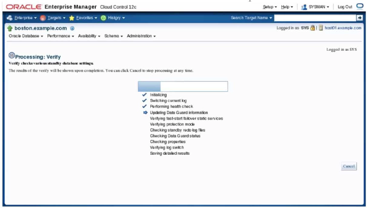
The screenshot above shows the progress indicator of the Verify Configuration administrative task that can be invoked from the Data Guard administration page. The verify configuration task performs a series of validation checks on the Data Guard configuration, including a health check of each database and agent. The Verify Configuration operation:
- Determines the current data protection mode settings, including the current redo transport mode settings for each database and whether the standby redo logs are configured properly. If standby redo logs are needed for a database, a message indicates this on the Detailed Results page. You can then add the standby redo logs.
- Validates each database for the current status
- Performs a log switch on the primary database (for non-RAC databases) and verifies that the log was applied on each standby database
- Checks the agent status for each database. The verify process executes a SQL*Plus job on the agent if credentials are available. If credentials are not available to run the job, the agent is pinged instead. If errors occur, a message appears on the Results page.
- Displays the results of the Verify Configuration operation (including errors)
Performing Routine Maintenance
You can use Enterprise Manager Cloud Control 12c to maintain your broker configuration. Each task is described in detail in the next few sections.
Configuring Fast-Start Failover
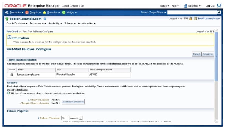
Enterprise Manager Cloud Control 12c can manage the Fast-Start Failover feature for Data Guard. The screenshot above shows the Configure page for Fast-Start Failover. It allows you to specify which standby database Fast-Start failure will use as the failover target, which host and alternate host will be used for the Data Guard observer process, failover properties, and primary database properties related to the Fast-Start Failover configuration.
Editing Primary Database Properties: General Properties
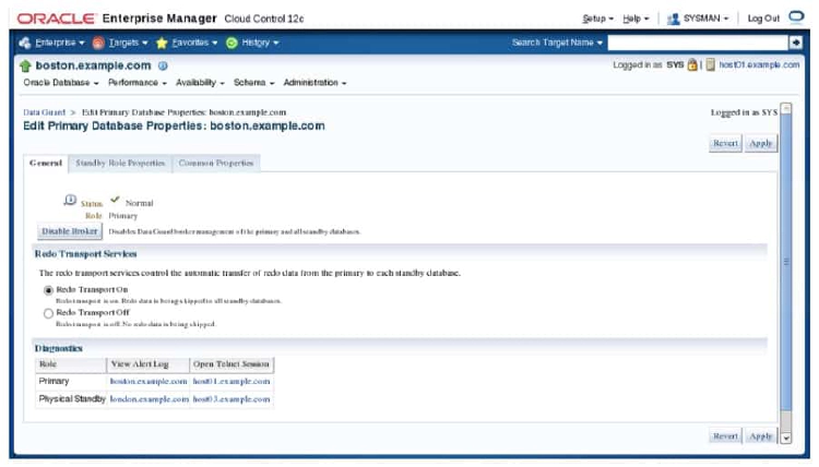
Enterprise Manager Cloud Control 12c can manage primary database properties related to the Data Guard configuration. In order to access the Edit Primary Database Properties page, navigate to the Data Guard administration home page of the primary database and click the Edit link beside the properties label of the primary database section. The screenshot above shows the General tab for editing primary database properties. There is also a Standby Role Properties tab and a Common Properties tab. The General tab allows the broker to be disabled or enabled, redo transport to be started or stopped, and allows viewing of the alert log of the primary database and standby database.
Editing Primary Database Properties: Standby Role Properties
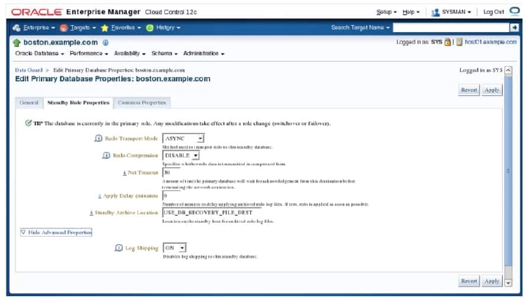
Additional Data Guard parameters that can be edited for the primary database can be found on the Standby Role properties tab and the common properties tab. The screenshot above shows the Standby Role Properties tab found on The Edit Primary Database Properties page. On this tab you can set the redo transport mode to SYNC, FASTSYNC, or ASYNC, the Redo Compression setting to ENABLE or DISABLE, and you can specify the number of seconds for Net Timeouts and the number of minutes for the Apply Delay. You can also specify the Standby Archive location and turn on or turn off log shipping to the standby database. The setting for standby archive location will only take effect after a role reversal, which allows the current primary database to become a standby database.
Editing Primary Database Properties: Common Properties
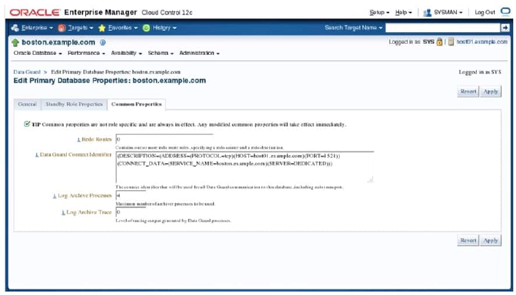
The screenshot above shows the Common Properties tab of the Edit Primary Database Properties page. On this tab, you can define redo routes, the Data Guard connect identifier for the primary database, the number of log archive process, and the trace level for Data Guard processes.
Test Application
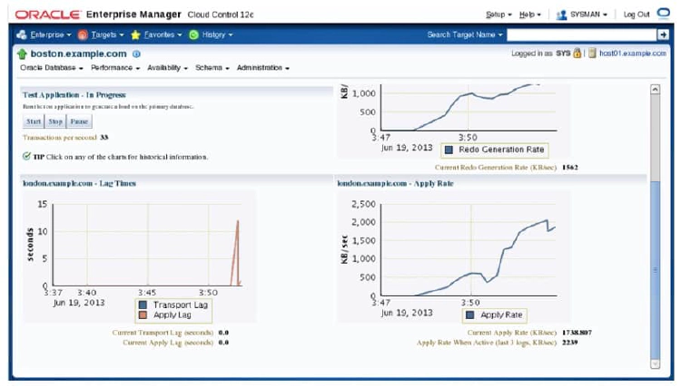
The test application feature of Oracle Enterprise Manager on the Data Guard administration webpage allows thorough testing of Data Guard by generating a workload on the primary database. This workload will generation many transactions per second, cause log switching at the primary, and monitor the reception of the redo on the standby database and the application of the received redo. The screenshot above shows the test application page in the progress of a running test. You have the ability to start, stop, or pause the test application. Statistics show the current transactions per minute (33 in the screenshot). There are three graphs on this page. The first graph shows the redo generation rate on the primary database measured in kilobytes per second. The second graph shows both the current transport lag and current apply lag measured in seconds on the standby database. The third graph shows the apply rate measure in kilobytes per second on the standby database.