Fundamental concepts of network addressing and routing for a Linux Server
TCP/IP Network Model
The TCP/IP network model is a simplified, four-layered set of abstractions that describes how different protocols interoperate in order for computers to send traffic from one machine to another over the Internet. The four layers are:
Application
Each application has specifications for communication so that clients and servers may communicate across platforms. Common protocols include SSH (remote login), HTTPS (secure web), NFS or CIFS (file sharing), and SMTP (electronic mail delivery).
Transport
Transport protocols are TCP and UDP. TCP is reliable connection-oriented communication, while UDP is a connectionless datagram protocol. Application protocols use TCP or UDP ports. A list of well-known and registered ports can be found in the /etc/services file. When a packet is sent on the network, the combination of the service port and IP address forms a socket. Each packet has a source socket and a destination socket. This information can be used when monitoring and filtering.
Internet
The Internet, or network layer, carries data from the source host to the destination host. The IPv4 and IPv6 protocols are Internet layer protocols. Each host has an IP address and a prefix used to determine network addresses. Routers are used to connect networks.
Link
The link, or media access, layer provides the connection to physical media. The most common types of networks are wired Ethernet (802.3) and wireless WLAN (802.11). Each physical device has a hardware address (MAC) which is used to identify the destination of packets on the local network segment.
Describing Network Interface Names
Each network port on a system has a name, which you use to configure and identify it. Older versions of CentOS/RHEL used names like eth0, eth1, and eth2 for each network interface. The name eth0 was the first network port detected by the operating system, eth1 the second, and so on. However, as devices are added and removed, the mechanism detecting devices and naming them could change which interface gets which name. Furthermore, the PCIe standard does not guarantee the order in which PCIe devices will be detected on boot, which could change device naming unexpectedly due to variations during device or system startup.
Newer versions of CentOS/RHEL use a different naming system. Instead of being based on detection order, the names of network interfaces are assigned based on information from the firmware, the PCI bus topology, and type of network device.
Network interface names start with the type of interface:
- Ethernet interfaces begin with en
- WLAN interfaces begin with wl
- WWAN interfaces begin with ww
The rest of the interface name after the type will be based on information provided by the server’s firmware or determined by the location of the device in the PCI topology.
- oN indicates that this is an on-board device and the server’s firmware provided index number N for the device. So eno1 is on-board Ethernet device 1. Many servers will not provide this information.
- sN indicates that this device is in PCI hotplug slot N. So ens3 is an Ethernet card in PCI hotplug slot 3.
- pMsN indicates that this is a PCI device on bus M in slot N. So wlp4s0 is a WLAN card on PCI bus 4 in slot 0. If the card is a multi-function device (possible with an Ethernet card with multiple ports, or devices that have Ethernet plus some other functionality), you may see fN added to the device name. So enp0s1f0 is function 0 of the Ethernet card on bus 0 in slot 1. There might also be a second interface named enp0s1f1 that is function 1 of that same device.
Persistent naming means that once you know what the name is for a network interface on the system, you also know that it will not change later. The trade off is that you cannot assume that a system with one interface will name that interface eth0.
IPv4 Networking
IPv4 is the primary network protocol used on the Internet today. You should have at least a basic understanding of IPv4 networking in order to manage network communication for your servers.
IPv4 Addresses
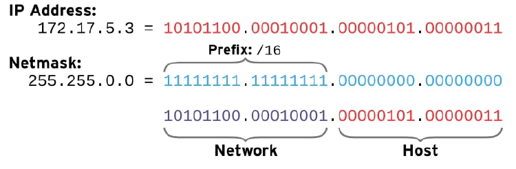
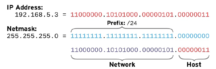
An IPv4 address is a 32-bit number, normally expressed in decimal as four 8-bit octets ranging in value from 0 to 255, separated by dots. The address is divided into two parts: the network part and the host part. All hosts on the same subnet, which can talk to each other directly without a router, have the same network part; the network part identifies the subnet. No two hosts on the same subnet can have the same host part; the host part identifies a particular host on a subnet.
In the modern Internet, the size of an IPv4 subnet is variable. To know which part of an IPv4 address is the network part and which is the host part, an administrator must know the netmask, which is assigned to the subnet. The netmask indicates how many bits of the IPv4 address belong to the subnet. The more bits available for the host part, the more hosts can be on the subnet.
The lowest possible address on a subnet (host part is all zeros in binary) is sometimes called the network address. The highest possible address on a subnet (host part is all ones in binary) is used for broadcast messages in IPv4, and is called the broadcast address. Network masks are expressed in two forms. The older syntax for a netmask uses 24 bits for the network part and reads 255.255.255.0. A newer syntax, called CIDR notation, specifies a network prefix of /24. Both forms convey the same information; namely, how many leading bits in the IP address contribute to its network address.
The following examples illustrate how the IP address, prefix (netmask), network part, and host part are related.
Calculating the network address for 192.168.1.107/24
| Host addr | 192.168.1.107 | 11000000.10101000.00000001.01101011 |
|---|---|---|
| Network prefix | /24 (255.255.255.0) | 11111111.11111111.11111111.00000000 |
| Network addr | 192.168.1.0 | 11000000.10101000.00000001.00000000 |
| Broadcast addr | 192.168.1.255 | 11000000.10101000.00000001.11111111 |
Calculating the network address for 10.1.1.18/8
| Host addr | 10.1.1.18 | 00001010.00000001.00000001.00010010 |
|---|---|---|
| Network prefix | /8 (255.0.0.0) | 11111111.00000000.00000000.00000000 |
| Network addr | 10.0.0.0 | 00001010.00000000.00000000.00000000 |
| Broadcast addr | 10.255.255.255 | 00001010.11111111.11111111.11111111 |
Calculating the network address for 172.16.181.23/19
| Host addr | 172.168.181.23 | 10101100.10101000.10110101.00010111 |
|---|---|---|
| Network prefix | /19 (255.255.224.0) | 11111111.11111111.11100000.00000000 |
| Network addr | 172.168.160.0 | 10101100.10101000.10100000.00000000 |
| Broadcast addr | 172.168.191.255 | 10101100.10101000.10111111.11111111 |
The special address 127.0.0.1 always points to the local system (“localhost”), and the network 127.0.0.0/8 belongs to the local system, so that it can talk to itself using network protocols.
IPv4 Routing
Whether using IPv4 or IPv6, network traffic needs to move from host to host and network to network. Each host has a routing table, which tells it how to route traffic for particular networks. A routing table entry lists a destination network, which interface to use when sending traffic, and the IP address of any intermediate router required to relay a message to its final destination. The routing table entry matching the destination of the network traffic is used to route it. If two entries match, the one with the longest prefix is used.
If the network traffic does not match a more specific route, the routing table usually has an entry for a default route to the entire IPv4 Internet: 0.0.0.0/0. This default route points to a router on a reachable subnet (that is, on a subnet that has a more specific route in the host’s routing table).
If a router receives traffic that is not addressed to it, instead of ignoring it like a normal host, it forwards the traffic based on its own routing table. This may send the traffic directly to the destination host (if the router happens to be on the destination’s subnet), or it may be forwarded on to another router. This process of forwarding continues until the traffic reaches its final destination.
Example routing table
| DESTINATION | INTERFACE | ROUTER (IF NEEDED) |
|---|---|---|
| 192.0.2.0/24 | wlo1 | N/A |
| 192.168.5.0/24 | enp3s0 | N/A |
| 0.0.0.0/0 (default) | enp3s0 | 192.168.5.254 |
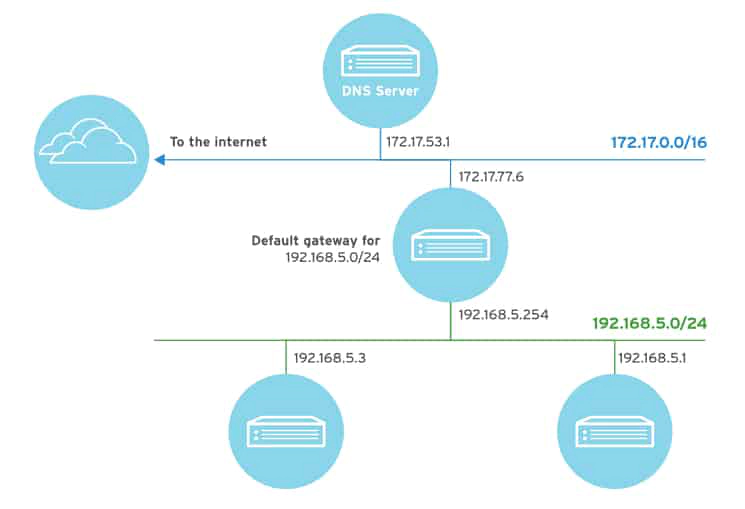
In this example, traffic headed for the IP address 192.0.2.102 from this host is transmitted directly to that destination via the wlo1 wireless interface, because it matches the 192.0.2.0/24 route most closely. Traffic for the IP address 192.168.5.3 is transmitted directly to that destination via the enp3s0 Ethernet interface because it matches the 192.168.5.0/24 route most closely.
Traffic to the IP address 10.2.24.1 is transmitted out the enp3s0 Ethernet interface to a router at 192.168.5.254, which forwards that traffic on to its final destination. That traffic matches the 0.0.0.0/0 route most closely, as there is not a more specific route in the routing table of this host. The router uses its own routing table to determine where to forward that traffic to next.
IPv4 Address and Route Configuration
A server can automatically configure its IPv4 network settings at boot time from a DHCP server. A local client daemon queries the link for a server and network settings and obtains a lease to use those settings for a specific length of time. If the client does not request a renewal of the lease periodically, it might lose its network configuration settings.
As an alternative, you can configure a server to use a static network configuration. In this case, network settings are read from local configuration files. You must get the correct settings from your network administrator and update them manually as needed to avoid conflicts with other servers.
IPV6 NETWORKING
IPv6 is intended as an eventual replacement for the IPv4 network protocol. You will need to understand how it works since increasing numbers of production systems use IPv6 addressing. For example, many ISPs already use IPv6 for internal communication and device management networks in order to preserve scarce IPv4 addresses for customer purposes.
IPv6 can also be used in parallel with IPv4 in a dual-stack model. In this configuration, a network interface can have an IPv6 address or addresses as well as IPv4 addresses. Red Hat Enterprise Linux operates in a dual-stack mode by default.
IPv6 Addresses
An IPv6 address is a 128-bit number, normally expressed as eight colon-separated groups of four hexadecimal nibbles (half-bytes). Each nibble represents four bits of the IPv6 address, so each group represents 16 bits of the IPv6 address.
2001:0db8:0000:0010:0000:0000:0000:0001
To make IPv6 addresses easier to write, leading zeros in a colon-separated group do not need to be written. However, at least one hexadecimal digit must be written in each colon-separated group.
2001:db8:0:10:0:0:0:1
Since addresses with long strings of zeros are common, one or more consecutive groups of zeros only may be combined with exactly one :: block.
2001:db8:0:10::1
Notice that under these rules, 2001:db8::0010:0:0:0:1 would be another less convenient way to write the example address. But it is a valid representation of the same address, and this can confuse administrators new to IPv6. Some tips for writing consistently readable addresses:
- Suppress leading zeros in a group.
- Use :: to shorten as much as possible.
- If an address contains two consecutive groups of zeros, equal in length, it is preferred to shorten the leftmost groups of zeros to :: and the rightmost groups to :0: for each group.
- Although it is allowed, do not use :: to shorten one group of zeros. Use :0: instead, and save :: for consecutive groups of zeros.
- Always use lowercase letters for hexadecimal numbers a through f.
IPv6 Subnetting
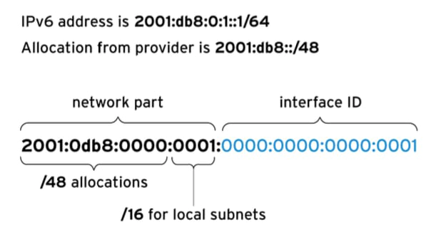
A normal IPv6 unicast address is divided into two parts: the network prefix and interface ID. The network prefix identifies the subnet. No two network interfaces on the same subnet can have the same interface ID; the interface ID identifies a particular interface on the subnet.
Unlike IPv4, IPv6 has a standard subnet mask, which is used for almost all normal addresses, /64. In this case, half of the address is the network prefix and half of it is the interface ID. This means that a single subnet can hold as many hosts as necessary.
Typically, the network provider will allocate a shorter prefix to an organization, such as a /48. This leaves the rest of the network part for assigning subnets (always of length /64) from that allocated prefix. For a /48 allocation, that leaves 16 bits for subnets (up to 65536 subnets).
Common IPv6 Addresses and Networks
| IPV6 ADDRESS OR NETWORK | PURPOSE | DESCRIPTION |
|---|---|---|
| ::1/128 | localhost | The IPv6 equivalent to 127.0.0.1/8, set on the loopback interface. |
| :: | The unspecified address | The IPv6 equivalent to 0.0.0.0. For a network service, this could indicate that it is listening on all configured IP addresses. |
| ::/0 | The default route (the IPv6 Internet) | The IPv6 equivalent to 0.0.0.0/0. The default route in the routing table matches this network; the router for this network is where all traffic, for which there is no better route, is sent. |
| 2000::/3 | Global unicast addresses | “Normal” IPv6 addresses are currently being allocated from this space by IANA. This is equivalent to all the networks ranging from 2000::/16 through 3fff::/16. |
| fd00::/8 | Unique local addresses (RFC 4193) | IPv6 has no direct equivalent of RFC 1918 private address space, although this is close. A site can use these to self-allocate a private routable IP address space inside the organization, but these networks cannot be used on the global Internet. The site must randomly select a /48 from this space, but it can subnet the allocation into /64 networks normally. |
| fe80::/10 | Link-local addresses | Every IPv6 interface automatically configures a link-local unicast address that only works on the local link on the fe80::/64 network. However, the entire fe80::/10 range is reserved for future use by the local link. This will be discussed in more detail later. |
| ff00::/8 | Multicast | The IPv6 equivalent to 224.0.0.0/4. Multicast is used to transmit to multiple hosts at the same time, and is particularly important in IPv6 because it has no broadcast addresses. |
A link-local address in IPv6 is an unroutable address used only to talk to hosts on a specific network link. Every network interface on the system is automatically configured with a link-local address on the fe80::/64 network. To ensure that it is unique, the interface ID of the link-local address is constructed from the network interface’s Ethernet hardware address. The usual procedure to convert the 48-bit MAC address to a 64-bit interface ID is to invert bit 7 of the MAC address and insert ff:fe between its two middle bytes.
- Network prefix: fe80::/64
- MAC address: 00:11:22:aa:bb:cc
- Link-local address: fe80::211:22ff:feaa:bbcc/64
The link-local addresses of other machines can be used like normal addresses by other hosts on the same link. Since every link has a fe80::/64 network on it, the routing table cannot be used to select the outbound interface correctly. The link to use when talking to a link-local address must be specified with a scope identifier at the end of the address. The scope identifier consists of % followed by the name of the network interface.
For example, to use ping6 to ping the link-local address fe80::211:22ff:feaa:bbcc using the link connected to the ens3 network interface, the correct command syntax is the following:
[user@host ~]$ ping6 fe80::211:22ff:feaa:bbcc%ens3
Multicast allows one system to send traffic to a special IP address that is received by multiple systems. It differs from broadcast since only specific systems on the network receive the traffic. It also differs from broadcast in IPv4 since some multicast traffic might be routed to other subnets, depending on the configuration of your network routers and systems.
Multicast plays a larger role in IPv6 than in IPv4 because there is no broadcast address in IPv6. One key multicast address in IPv6 is ff02::1, the all-nodes link-local address. Pinging this address sends traffic to all nodes on the link. Link-scope multicast addresses (starting ff02::/8) need to be specified with a scope identifier, just like a link-local address.
[user@host ~]$ ping6 ff02::1%ens3
PING ff02::1%ens3(ff02::1) 56 data bytes
64 bytes from fe80::211:22ff:feaa:bbcc: icmp_seq=1 ttl=64 time=0.072 ms
64 bytes from fe80::200:aaff:fe33:2211: icmp_seq=1 ttl=64 time=102 ms (DUP!)
64 bytes from fe80::bcd:efff:fea1:b2c3: icmp_seq=1 ttl=64 time=103 ms (DUP!)
64 bytes from fe80::211:22ff:feaa:bbcc: icmp_seq=2 ttl=64 time=0.079 ms
...output omitted...
IPv6 Address Configuration
IPv4 has two ways in which addresses get configured on network interfaces. Network addresses may be configured on interfaces manually by the administrator, or dynamically from the network using DHCP. IPv6 also supports manual configuration, and two methods of dynamic configuration, one of which is DHCPv6.
Interface IDs for static IPv6 addresses can be selected at will, just like IPv4. In IPv4, there are two addresses on a network that could not be used: the lowest address in the subnet and the highest address in the subnet. In IPv6, the following interface IDs are reserved and cannot be used for a normal network address on a host.
- The all-zeros identifier 0000:0000:0000:0000 (“subnet router anycast”) used by all routers on the link. (For the 2001:db8::/64 network, this would be the address 2001:db8::)
- The identifiers fdff:ffff:ffff:ff80 through fdff:ffff:ffff:ffff.
DHCPv6 works differently than DHCP for IPv4, because there is no broadcast address. Essentially, a host sends a DHCPv6 request from its link-local address to port 547/UDP on ff02::1:2, the all-dhcp-servers link-local multicast group. The DHCPv6 server then usually sends a reply with appropriate information to port 546/UDP on the client’s link-local address.
In addition to DHCPv6, IPv6 also supports a second dynamic configuration method, called Stateless Address Autoconfiguration (SLAAC). Using SLAAC, the host brings up its interface with a linklocal fe80::/64 address normally. It then sends a “router solicitation” to ff02::2, the allrouters link-local multicast group. An IPv6 router on the local link responds to the host’s link-local address with a network prefix and possibly other information. The host then uses that network prefix with an interface ID that it normally constructs in the same way that link-local addresses are constructed. The router periodically sends multicast updates (“router advertisements”) to confirm or update the information it provided.
Host Names and IP Addresses
It would be inconvenient if you always had to use IP addresses to contact your servers. Humans generally would prefer to work with names than long and hard-to-remember strings of numbers. And so Linux has a number of mechanisms to map a hostname to an IP address, collectively called name resolution. One way is to set a static entry for each name in the /etc/hosts file on each system. This requires you to manually update each server’s copy of the file.
For most hosts, you can look up the address for a hostname (or a hostname from an address) from a network service called the Domain Name System (DNS). DNS is a distributed network of servers providing mappings of hostnames to IP addresses. In order for name service to work, a host needs to be pointed at a nameserver. This nameserver does not need to be on the same subnet; it just needs to be reachable by the host. This is typically configured through DHCP or a static setting in a file called /etc/resolv.conf.